
Quick Summary
High line pressure and differential pressure are not the same. The precise loss depends on the range chosen, the effect of temperature and proper fittings. It also depends on calibration so that small losses can be accurately measured.
A pressurized system can look healthy while a filter quietly restricts flow. A high line pressure transducer helps identify that restriction by measuring a small pressure difference within a much higher operating pressure. Achieving useful accuracy requires more than choosing a sensor that withstands pipeline pressure.
What a High Line Pressure Transducer Measures
Line pressure is the pressure acting on the sensor ports during operation. Differential pressure is the difference between those ports, often across a filter, valve, or flow restriction. A sensor must handle the first while accurately resolving the second.
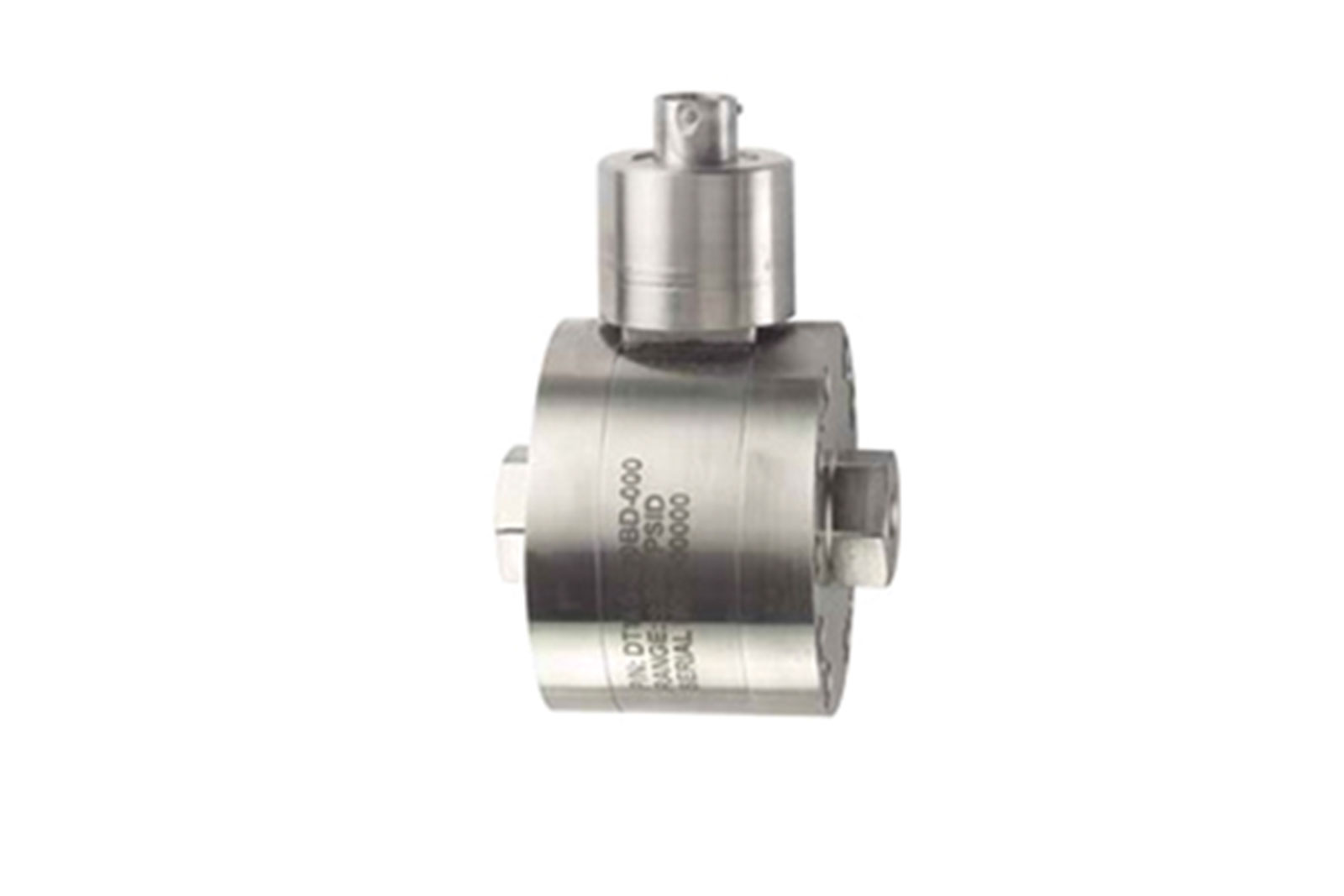
Our DT140 differential pressure transducer at Stellar Technology combines wet-to-wet measurement, high line pressure capability, and a millivolt-per-volt output. Removable ports let you inspect and clean the sensor.
Imagine a filter with 2,000 psi upstream and 1,995 psi downstream. What matters is the 5-psi differential; both ports still see about 2,000 psi. A sensor with a five-psi differential range must still tolerate 2,000 psi at both ports.
Why Subtracting Two Readings Can Hide Changes
Two pressure sensors measure upstream and downstream pressure. However, each reading has uncertainty, and subtracting them increases the combined uncertainty in the calculated difference. Small changes become difficult to distinguish when the underlying measurements span thousands of psi.
Suppose each hypothetical 3,000-psi sensor has an error limit of ±0.25% of full scale. That equals ±7.5 psi per sensor. Opposing errors could shift the calculated difference off by 15 psi, greater than the 5 psi drop under investigation.
Direct differential measurement sets the instrument range to the expected difference. It can reduce this particular problem, although line pressure effects and temperature errors still need assessment. The improvement depends on the measurement design, not the product label.
Match the Range to the Actual Task
Start with the smallest pressure change that will affect an operating decision. Then identify normal differential pressure, maximum differential pressure, and maximum port pressure. These values answer different questions and should appear separately in the purchase specification.
The extra range increases absolute uncertainty when accuracy is given as a percentage of full scale, so don’t choose excess range just because it seems safer. Compare the required measurement tolerance with errors in psi, and note which term dominates the uncertainty before finalizing the selection.
Distinguish between equal pressure at both ports and situations where full line pressure is applied to only one port; verify permissible loading for both conditions.
Ask how common line pressure affects the zero and span specifications for the selected configuration. Treat it as part of the uncertainty analysis. A sensor can remain mechanically intact while its indicated difference shifts enough to affect the maintenance decision.
Keep Installation Errors Out of the Reading
A transducer can’t compensate for blocked tubing, trapped gas, or elevation errors; those change the pressure at the ports, so the reading may reflect the installation instead of the filter.
Keep connection paths appropriate for the fluid and the required response. Where possible, avoid unnecessary tubing length and position pressure taps consistently. Follow the specified filling, venting, and isolation procedures for the installation.
Temperature also deserves attention. A sensor calibrated in a controlled room may experience a hot process line and a cooler surrounding enclosure. Review its compensated temperature limits and account for conditions beyond them.
For bridge-output sensors, stable excitation and compatible signal conditioning matter. Incorrect gain can compress the usable signal range, while excessive filtering can hide changes. Verify the complete electrical chain before adjusting process thresholds.
Use Calibration to Check Real Performance
Calibration establishes how the output relates to known pressure differences. Review results across the operating range, rather than checking only zero and full scale. Increasing and decreasing pressure tests can reveal hysteresis that a single rising-pressure test misses.
Also ask how the sensor behaves under the expected common line pressure. A differential calibration near atmospheric pressure may not describe every effect of a pressurized installation. Include relevant conditions in the test plan where measurement tolerances demand them.
Our repair and calibration services can help assess sensors after drift, overload, or unexplained changes. Record the symptoms and operating conditions before sending a unit for evaluation.
Turn Small Pressure Changes Into Useful Decisions
Accurate differential readings help operators distinguish gradual restriction from ordinary process variation. Build the measurement around the pressure difference, then account for line pressure, temperature, installation, and electronics. That approach makes small changes useful enough to guide maintenance and operating decisions.
Choose the Right Sensor for Pressurized Systems
We manufacture DT140 differential pressure transducers at Stellar Technology for applications requiring high line pressure capability. Reach out to our team with your operating pressures and measurement tolerance to find the right differential sensor.
FAQs
Does high line pressure mean a large pressure difference?
No. Both ports can experience high pressure while the difference between them remains small, such as across a clean filter.
Can I calculate differential pressure with two ordinary sensors?
Yes, but evaluate their combined uncertainty. Subtracting large readings can make a small difference difficult to measure accurately.
What should I specify besides differential range?
Include maximum line pressure, possible one-sided overload, fluid compatibility, temperature, output type, and required measurement tolerance.