
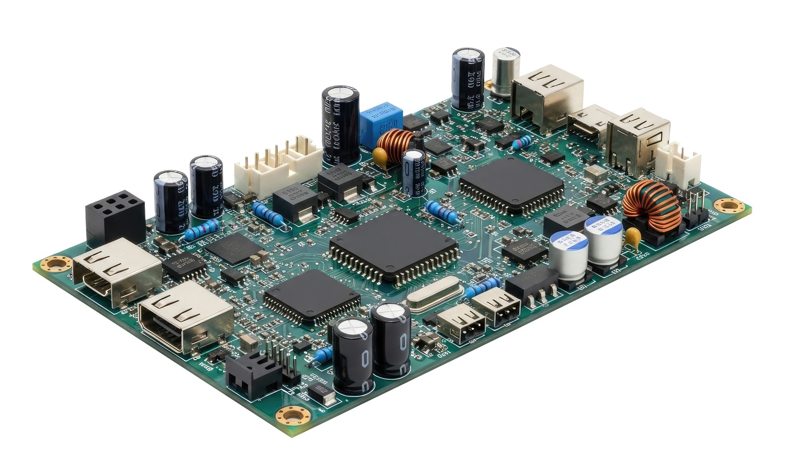
Amplification is what lets a 2 millivolt bridge output use a converter’s full span instead of a dozen counts, though gain amplifies noise alongside signal and only filtering separates them. Offset shifts readings by a fixed amount, gain error grows toward full scale, and thermal drift moves both as a cabinet warms, which is why amplifiers quote drift per degree. Tight filtering cleans a signal and delays it, so bandwidth has to match the phenomenon being measured. Ground potential differences create loops that produce believable but wrong readings, countered by isolation, common mode rejection, and current loop outputs.
Two engineers can buy the same transducer and still end up with very different numbers. Datasheet accuracy describes the element under controlled conditions, while the measurement you actually record passes through cable, electronics, and a converter before anyone sees it. Signal conditioning sits at the center of that journey and quietly decides how much of the sensor’s capability survives the trip. Specification sheets rarely make that contribution visible, which is part of the reason it gets overlooked during design reviews.
Curious where the error actually creeps into a measurement?
Signal to Noise Ratio and Usable Resolution
Converter datasheets quote resolution in counts rather than accuracy, and that difference becomes obvious the moment you connect a real sensor. A 16-bit converter spanning ten volts resolves roughly 150 microvolts per count, so a 2 millivolt full-scale bridge output would occupy barely a dozen counts without any amplification in front of it. Raising that output to fill the converter’s full input range puts the whole span to work, which is the single largest improvement that good conditioning has to offer.
Noise complicates the picture further, since amplifying the sensor output also amplifies whatever rode in alongside it, and only filtering can separate the two of them afterwards. Usable resolution in the field therefore comes from gain and noise rejection working together rather than from the converter specification standing alone on a datasheet.
Offset, Gain Error and Thermal Drift
Three separate error terms follow every analog measurement from end to end, and each of them behaves differently from the others. An offset shifts the entire reading by a fixed amount, so a sensor sitting quietly at rest still reports something other than a clean zero at the display. Gain error scales with the measurement itself, which means it hides at low readings and grows steadily toward the top of the working range. Thermal drift moves both of those terms as a cabinet warms through the working day, which is the reason amplifier specifications quote drift in parts per million per degree of temperature change. Conditioning can correct offset and gain at commissioning through zero and span adjustment, though only a low drift design keeps those corrections valid as conditions change around the panel itself.
Bandwidth, Filtering and Response Time
Speed and cleanliness pull against each other in every measurement chain, and the right balance changes with the application at hand. A tight low-pass filter removes interference beautifully, and it also delays the response, so a fast event arrives at the controller either late or softened beyond recognition. Static weighing tolerates that trade happily, while impact testing, vibration work, and fast pressure transients certainly do not tolerate it. Matching the conditioner bandwidth to the phenomenon you are chasing keeps both problems in proportion, since filtering below the signal frequency destroys information that nobody can recover afterwards. Settling behavior deserves a look as well, particularly in systems that switch between several channels, since each reading has to stabilize completely before the converter takes its sample and moves on.
Grounding, Isolation and Common Mode Rejection
Two pieces of equipment rarely share the same ground potential, and the difference between them becomes a current flowing quietly through your signal wiring. Ground loops of that kind add error that looks entirely legitimate at the display, which makes them much harder to catch than obvious interference does. A DC-to-DC converter inside the conditioner separates output from supply and breaks that path before it ever reaches the recording equipment. Common mode rejection handles a related problem, discarding voltage that appears equally on both input lines while keeping the small difference that carries the measurement. Choosing a current loop output adds a further layer, since current stays constant along the conductor and resists both voltage drop and induced interference along the way.
Turn a Good Sensor Into a Trustworthy Measurement
Accuracy survives the trip from element to controller only when gain, filtering, isolation, and drift are all handled deliberately rather than left to chance. Stellar Technology designs sensors and the electronics together, which means the conditioner and the transducer are specified as one measurement system rather than two separate purchases. Our instrumentation line runs from the AP5103 general purpose rail conditioner through the AP5201 in-line amplifier with its switchable output, and our readout instrumentation covers handheld meters through 6-digit panel displays. Calibration and repair for equipment already in service are handled by the same Amherst facility that built it in the first place.
If your readings drift or look noisier than they should, send us the setup and we will quote a cleaner chain for free.
FAQs
Does a higher resolution converter improve accuracy on its own?
Not by itself. Resolution describes counts, not correctness, and a two millivolt bridge output would occupy only a handful of counts across a ten volt input span. Amplifying to fill that span puts the whole converter to work. Noise rejection has to come along too, since gain raises interference alongside the measurement.
What is the difference between offset and gain error?
Offset adds a fixed amount to every reading, so a sensor at rest reports something other than zero. Gain error scales with the measurement, staying invisible at low readings and growing toward the top of the range. Zero and span adjustment corrects both at commissioning, though thermal drift can move them again afterwards.
How do I choose a filter cutoff?
Start from the fastest event you need to capture and set the cutoff above it. Filtering below the signal frequency removes information nobody can recover later. Static measurements such as weighing tolerate heavy filtering comfortably, while impact testing, vibration work and fast pressure transients do not. Settling time also counts in multiplexed systems.